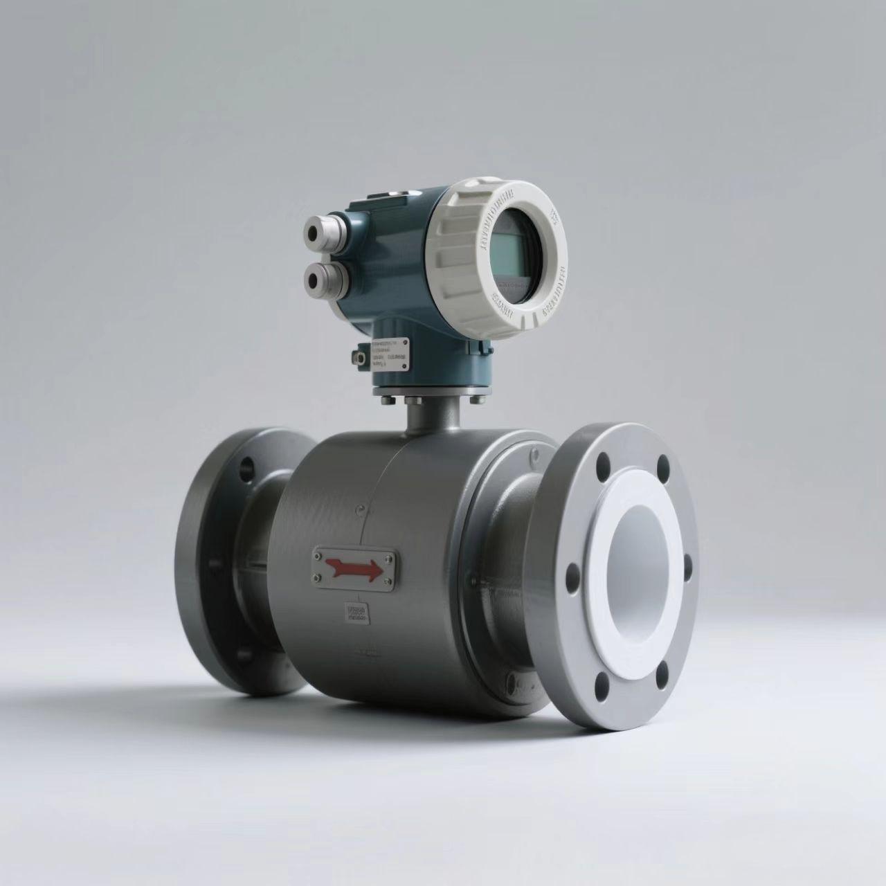
Electromagnetic flowmeter
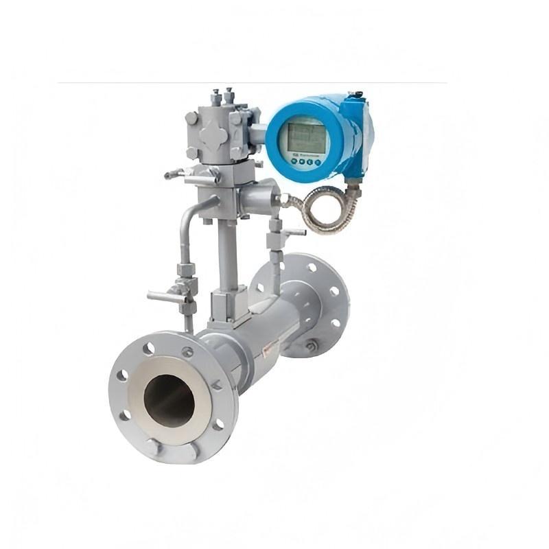
The structure of the electromagnetic flowmeter mainly consists of; magnetic circuit system, measuring conduit, electrodes, housing, lining, and transmitter.
Magnetic Circuit System: It consists of a dual-frequency excitation field superimposed by high and low-frequency rectangular wave currents, offering excellent stability, no flow noise interference, and good response characteristics.
Measuring Conduit: Its function is to allow the conductive liquid being measured to pass through. To prevent magnetic flux from being shunted or short-circuited when magnetic lines of force pass through the measuring conduit, the measuring conduit must be made of non-magnetic, low-conductivity, low-thermal-conductivity materials with a certain mechanical strength. Our company mainly selects non-magnetic stainless steel and aluminum.
Electrodes: Their function is to draw out the induced electromotive force (EMF) signal, which is proportional to the measured quantity. The electrodes are made of non-magnetic stainless steel and are required to be flush with the lining to ensure unobstructed fluid flow. They are installed in the vertical direction of the pipeline to prevent sediment accumulation from affecting measurement accuracy.
Housing: Made of ferromagnetic material, it serves as the outer cover for the excitation coils and isolates interference from external magnetic fields.
Lining: On the inner side of the measuring conduit and the flange sealing surface, there is a complete electrical insulating lining. It directly contacts the measured liquid, and its function is to increase the corrosion resistance of the measuring conduit and prevent the induced electromotive force from being short-circuited by the metal wall of the measuring conduit. The lining material is made of PTFE (polytetrafluoroethylene) or neoprene rubber.
Transmitter: It amplifies the induced electromotive force signal, converts it into a unified standard electrical signal, and suppresses interference signals. Its task is to amplify the induced electromotive force signal Ex detected by the electrodes and convert it into a unified standard DC signal.
Features
1. Unaffected by changes in fluid density, viscosity, temperature, pressure, and conductivity;
2. No obstructing flow parts inside the pipe, no pressure loss, low requirements for straight pipe sections, and unique adaptability for slurry measurement;
3. Good corrosion and wear resistance can be achieved by reasonably selecting lining and electrode materials;
4. The transmitter adopts an excitation method, featuring low power consumption, stable zero point, and high accuracy. The flow rangeability can reach 150:1;
5. The transmitter and electrode tube can be integrated or separated;
6. The transmitter converts signals into 4-20mA d.c. current (with HART communication superimposed), PROFIBUS-PA communication signals, and FF communication signal output, allowing for remote parameter setting and monitoring, convenient setup, and reliable programming;
7. The transmitter adopts Surface Mount Technology (SMT) and has self-check and self-diagnosis functions;
8. Measurement accuracy is unaffected by changes in fluid density, viscosity, temperature, pressure, and conductivity; the induced signal has a linear relationship with the average flow rate, resulting in high measurement accuracy.
9. There are no flow-obstructing parts inside the measuring pipe, thus no additional pressure loss; there are no moving parts inside the measuring pipe, thus the sensor has an extremely long lifespan.